Top
Week 1
Learning Aims and Objectives:
Aim: In this week's page, students will learn the
Objectives:
1. By the end of this week's page students will be able to.
2. By the end of the week's page students will be able to.
P3.1 Fault analysis tools and their applications to identify problems
Why do companies need to use tools to monitor and analyse faults? Is it not better to have a system that alerts when there are just faults and then they can be fixed? The answer to these questions is quite simple, not all faults that are the same are triggered in the same way. We must remember that at any one time, a network, computer or digital device could be processing any number of actions in the background that users might not be aware of. The use of tools to monitor and analyse faults provides engineers and technicians an opportunity to reflect on the logs of the systems to understand potential triggers.
Have you ever had a situation where you have had a fault and someone else has also experienced it? Were they triggered at the same time? Were you both working on the same thing with the same applications or elements open? How did you resolve this issue? what was it? Was it the same process as the other person?
Having looked at and used some of the network/tone testers in a lab setting, research and review the different testers available and the features and functions that they have and can do. Discuss where these might be used and the benefits to the users.
How are faults identified on the systems that we use? Let's look into the most common.
Traditional Techniques used to fault find used flow charts to ask users questions to discount or discredit areas that the issue wasn't. These flow charts were significant in thier breath of the topic area, and became almost obsolete due to the large amount of variables and possible resolutions. However a flow chart can be seen in action to help Sheldon find a friend.
System alerts
A flag when a system condition is outside predetermined parameters
Common system alerts come in the form of beep codes, these codes act like a morse code for technicians. The codes themselves are short and long pulses of sound generated by a small speaker mounted to the main circuit board.
On newer devices small lcd screens display codes that can be cross referenced against the manufacturers information doucmentations provided with the device or online.
Flow Chart Operators


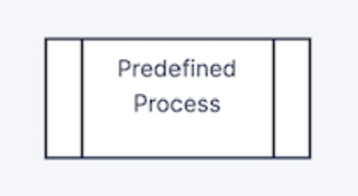

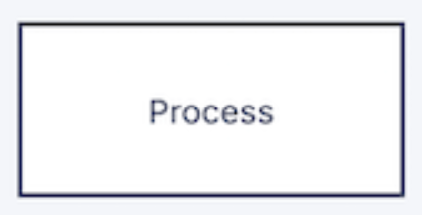
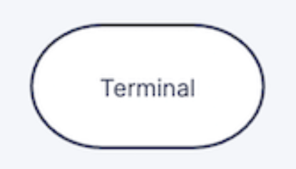
Lets consider the use of flowcharts to support the resolution of a sound card. Using the flow chart notation above create a chart that some one could use to fix a sound card issue.
Activity/error logs
Record of all interactions and events within network systems
The importance of logging only to clear to reflect on possible clues to the lead up to faults and thier diagnosis. Within the educational sector a shared academic network called "Janet" is used. This network is operated and supported by the Jisc group and is governed by UKERNA (United Kingdom Education and Research Networking Association), which is a nonprofit group of the U.K. Higher Education Funding Council.
Within Jisc website they have a series of support documentation that further discusses the use and need for the use of Activity/error logs
Jisc Activity and Error loggingResearch using the link above what areas are suggested for those that use and work with the Janet network to log.
What do these logs look like and what files are they?
Log files are not formatted documents that present information in pretty headings and images in most examples. These files tend to have rows of information that is separated over lines for different logged data. As you are able to see in the image below the log is identifying the date time that the log recorded something and a message of the error that was logged and what the user might have been trying to access.
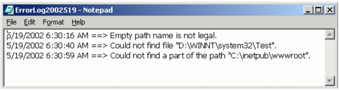
In most situations the log files for networks and programs are basic text files, that if attempted to be opened, would in a windows environment by opened in notepad. The files are automatically generated by the systems at specific times and if needed manually.
Live traces
identify any network traffic or activity in real-time
Network traffic can be monitored when its working in real time but what about when it isn't!?
Case Study:
Installation of the network and electrical infrastructure for the T-Level room:
Prior to the creation of a bespoke room for the delivery of the NCFE Digital Support Services T-Level program a college bought in a contractor to set up network and PowerPoints in a range of places in the room to enable the placement of IT equipment in new locations from the original that previously existed in the room. These network faceplates had 2 connections that ran back to a patch panel located in the server room. These patch panels where then connected via patch cables to 10 gigabit switches that ran 10 gigabit SFP+ fiber cables to a fibre switch that connected to the main servers within the organisation. The problems occurred around a week after the PC's were set up in the classroom, some of the networked and previously functional PC's showed no network activity. The initial thoughts around this issue was that the network port had been damaged in some way, so a simple fault remedy was suggested of changing to another port in the network faceplate. However, this didn't resolve the issue, so it was suggested to try the next available port, suprisingly the issue remained. The next step was to swap out the cable for another that was known to work, and test this on all ports used previously. The result was still the same! Next was to try another PC in case the network interface card in the PC was faulty. Again this issue remianed.
Increasing frustrated with the result we used a network/tone tester to check the cable. The tester sends pulses of electrical current down the cable with a transmitter that at the other end the receiver lights up the cable strands that are connected. The result of this test identified that only 2 stands of the 8 were actually transmitting. This would suggest that the faceplate module may have loose connections in the back. On opening up the faceplate it was clear that the cable had been adjusted using electrical cable joiners to extend the cable that was then connected to the faceplate module. The next step was to remove those connectors and to cable directly to the faceplate module the strands of wire and remove the extensions completely. Hopeful that this would be the fix the cable was then checked and tested again. However this was not the case and still the issue remained, and the strands 5 and 6 were the only operational pair. What next!! The fault was still there what more can be done? The next step was to use a more advanced network testing tool that allows testing of the length of the cable in the hope that there is information on whether there is a break somewhere in the cable. This tool worked and identified that the cable had a break approximately 7.4 meters down the cable that should be 60 meters plus. This outcome although not resolved gave a result that suggested that the external contractor had rushed or installed incorrectly the new locations and networks ports and had impacted other ports by doing so.
The outcome of this fault diagnosis resulted in the temporary installation of a network switch in the room connected to 2 known working ports to enable a 2 gig connection that the PC's in the room could connect to whilst the contractor was bought back to reinstall and test the required structure.
Dashboards
A consolidated visual representation of system condition and performance
Last Updated
2024-09-24 13:22:29
English and Maths
English
Maths
Stretch and Challenge
Stretch and Challenge
Homework
Homework
Equality and Diversity Calendar
How to's
How to's Coverage
Links to Learning Outcomes |
Links to Assessment Criteria |
|
|---|---|---|
Files that support this week
→
Next